
-
-
 Cardiology
-
 Clinical Oncology
-
 Dental
-
 Dermatology
-
 Ear, Nose, Throat (ENT)
-
 Endocrinology
-
 Gastroenterology
-
 General Surgery
-
 Gynecology & Obstetrics
-
 Interventional Cardiology
-
 Nephrology
-
 Neurology
-
 Oncology Surgery
-
 Ophthalmology
-
 Orthopedics
-
 Pediatrics
-
 Pediatrics Surgery
-
 Physiotherapy
-
 Plastic Surgery
-
 Psychiatry & Psychology
-
 Radiology
-
 Urology
-
 Vascular Surgery
-

 Anatomy Lab Equipments
 Biochemistry Lab Equipments
 Biology Lab Equipments
 Chemistry Lab Equipments
 Cytology Lab Equipments
 Cytopathology Lab Equipments
 Dental Lab Equipments
 Forensic Lab Equipments
 Genetics Lab Equipments
 Hematology Lab Equipments
 Histology Lab Equipments
 Histopathology Lab Equipments
 Mathematics Lab Equipments
 Microbiology Lab Equipments
 Molecular Biology Lab Equipments
 Pathology Lab Equipments
 Pharmaceutical Lab Equipments
 Physics Lab Equipments
 Radiology Lab Equipments
 Science Lab Kit’s
 Toxicology Lab Equipments

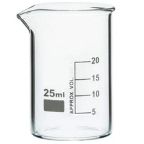 Borosilicate Glass Beaker
 Plastic Beaker (Euro Design)
 Plastic Beaker (Printed Graduation)
 Test Tube Brush
 Measuring Cylinder Brush
 Conical Flask Brush
 Volumetric Flask Brush
 Round Bottom Flask Brush
 Glass Beaker Brush
 Pipette Brush
 Wash Bottle Brush
 Borosilicate Büchner Flask
 Borosilicate Erlenmeyer/Conical Flask
 Borosilicate Pear-Shaped Flask
 Borosilicate Round Bottom Flask
 Plastic Conical Flask
 Plastic Volumetric Flask
 Bunsen Burner
 Spirit Lamp
 Borosilicate Glass Burette
 Plastic Burette
 Capillary Tube
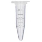 Centrifuge Tube
 Test Tube
 Ria Vial
 Vacutainer Tubes
 Syringes
 Student Microscope
 Binocular Microscope
 Dissecting Microscope
 Microscope Glass Slides
 Cover Slip
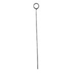 Inoculating Loop
 Slide Box
 Lamps
Lamps
 Oils
Oils
 Beaker Tongs
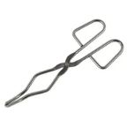
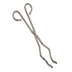 Crucible Tongs
 Flask Tongs
 Borosilicate Glass Funnel
 Plastic Funnels
 Wash Bottle
 Borosilicate Glass Reagent Bottle
 Plastic Reagent Bottle
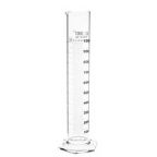
 Borosilicate Measuring Cylinder
 Plastic Measuring Cylinder
 Borosilicate Glass Graduated Pipette
 Borosilicate Glass Volumetric Pipette
 HB Pipette
 Pasteur Pipette
 Micropipettes
 Micropipette Tips
 Filter Paper
 Litmus Paper
 pH Paper
 Chromatography Paper
 Plastic Petri Plates (Sterile)
 Glass Petri Plates (Non-Sterile)
 Safety Goggles
 Lab Coats
 Gloves
 Masks
Masks
 Shoe Covers
 Hair & Beard Covers
 Steel Spatula
 Plastic Spatula
 Hitachi Sample Cup
 Plastic Scoop
 Plastic Medicine Cup
 Dissecting Tool Kit
 Dissecting Forceps
 Hemostatic Forceps
 Thumb Forceps / Tweezers
 Blood Culture Bottle
 Urine Container
 Wooden Swab Stick
 Test Tube Holder
 Test Tube Racks
 Magnifying Glass
 Watch Glass
 Mortar and Pestle
 Coplin Jar
 Plastic Stirrer
 Glass Stirrer
 Crucible
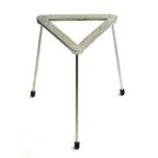 Tripod
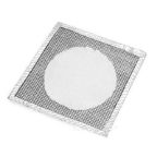 Wire Mesh
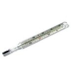 Laboratory Thermometer
 Tourniquet
 Alcohol Swab
 Blood Lancet
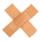 Bandage
 Gloves & Masks


Understanding Ohm’s Law Experiment: Electrical Principles Explored
Contents
- Introduction to Ohm’s Law and Its Significance
- Historical Background of Ohm’s Law
- Key Electrical Terms: Voltage, Current, and Resistance
- The Mathematical Foundation of Ohm’s Law
- Why Ohm’s Law Is Essential in Electrical Science
- Materials and Equipment Required for the Experiment
- Safety Guidelines Before Conducting the Experiment
- Setting Up the Ohm’s Law Circuit
- Step-by-Step Procedure for the Ohm’s Law Experiment
- Measuring Voltage Across a Resistor
- Calculating Current Flow Using Ohm’s Law
- Understanding Resistance in Practical Circuits
- Graphical Representation of Voltage vs. Current
- Analysing the Linear Relationship in Ohm’s Law
- Real-Life Applications of Ohm’s Law
- Common Errors and How to Avoid Them
- Troubleshooting Issues in the Experiment
- Importance of Accurate Measurements in Electrical Testing
- Variations of the Experiment Using Different Resistors
- Conclusion and Key Takeaways from the Experiment
- Advanced Concepts Related to Ohm’s Law
- Ohmic vs. Non-Ohmic Components Explained
- Understanding Limitations of Ohm’s Law
- Frequently Asked Questions About Ohm’s Law Experiment
Introduction to Ohm’s Law and Its Significance
Imagine a world where the flow of electricity is as predictable as water flowing through a pipe. That world exists thanks to Ohm’s Law, a fundamental principle that governs electrical circuits. Whether you’re an aspiring engineer, a curious student, or just someone fascinated by how things work, understanding Ohm’s Law is crucial.
This law not only illuminates the relationship between voltage, current, and resistance but also lays the groundwork for countless applications in technology and everyday life. So why should you care about this seemingly simple equation? Because it unlocks the door to better comprehension of electric systems around us—from your smartphone charger to complex power grids.
In this blog post, we will dive deep into Ohm’s Law through hands-on experimentation and exploration of its principles. Get ready to uncover insights that can enhance your knowledge and spark your creativity in electrical science!
Historical Background of Ohm’s Law
Ohm’s Law is named after Georg Simon Ohm, a German physicist and mathematician. In the 1820s, he conducted groundbreaking experiments that laid the foundation for electrical theory.
His most notable work appeared in his publication “Die galvanische Kette, mathematisch bearbeitet” in 1827. This document introduced the relationship between voltage, current, and resistance—essentially defining how electricity flows through conductive materials.
Ohm’s findings were initially met with skepticism. Many in the scientific community struggled to grasp their significance at first. However, as technology advanced and practical applications emerged, his principles gained recognition.
The law itself states that current is directly proportional to voltage and inversely proportional to resistance. This simple yet profound equation unlocked numerous possibilities within engineering and physics disciplines.
Today, Ohm’s contributions are crucial for understanding modern electronics. His legacy continues to influence innovations across multiple fields of science and technology.
Key Electrical Terms: Voltage, Current, and Resistance
Voltage, current, and resistance are fundamental concepts in electricity. Understanding these terms is crucial for anyone delving into electrical science.
Voltage, often referred to as electric potential difference, represents the energy available to push electric charges through a circuit. It’s measured in volts (V) and can be thought of as the pressure that pushes electrons along a conductor.
Current measures the flow of electric charge over time and is expressed in amperes (A). Picture it like water flowing through a pipe; more current means more electrons moving past a point each second.
Resistance opposes the flow of current and is measured in ohms (Ω). Think of it as friction within the circuit. High resistance reduces current flow while low resistance allows for easier passage of electricity. Together, these three elements form the backbone of Ohm’s Law, shaping our understanding of how circuits operate.
The Mathematical Foundation of Ohm’s Law
At the heart of Ohm’s Law lies a simple yet profound equation: V = I × R. Here, voltage (V) is measured in volts, current (I) in amperes, and resistance (R) in ohms. This relationship forms the backbone of electrical circuits.
Understanding this formula allows us to predict how electricity behaves under different conditions. If we increase the resistance while keeping voltage constant, current diminishes. Conversely, lowering resistance boosts current flow.
This mathematical foundation not only aids engineers but also empowers hobbyists and students experimenting with electronics at home. By manipulating these variables, one can see firsthand how changes affect circuit performance.
The beauty of Ohm’s Law lies in its simplicity. It provides an intuitive grasp of electrical principles that govern everything from household appliances to complex machinery used in industries today.
Why Ohm’s Law Is Essential in Electrical Science
Ohm’s Law is a cornerstone of electrical science. It provides a simple yet profound understanding of the relationship between voltage, current, and resistance.
This law enables engineers to design circuits with precision. By knowing how these three elements interact, they can predict circuit behavior under various conditions.
In practical applications, Ohm’s Law helps troubleshoot issues efficiently. When something goes wrong in an electrical system, this fundamental principle guides technicians toward identifying potential faults.
Additionally, it serves as a foundation for more complex theories in electronics and physics. Without grasping Ohm’s Law, delving into advanced topics would be daunting for students and professionals alike.
Moreover, its relevance extends beyond theoretical knowledge; it has significant implications in everyday technology—from household appliances to complex machinery found in industries. Understanding this basic principle empowers individuals to engage confidently with the world of electricity.
Materials and Equipment Required for the Experiment
To conduct the Ohm’s Law experiment, gather essential materials that will ensure accurate results. Start with a power supply. This can be a battery or a DC power source that provides consistent voltage.
Next, you’ll need resistors. Various resistor values allow for different experiments and insights into how resistance affects current flow.
A multimeter is crucial in this setup. It measures voltage and current with precision, helping to validate your findings efficiently.
Connecting wires are necessary for creating circuits. Choose insulated copper wires to prevent short-circuits while ensuring good conductivity.
Consider using a breadboard for easy circuit assembly without soldering. It allows flexibility when modifying connections during the experiment.
These tools create an effective environment for exploring electrical principles thoroughly and engagingly.
Safety Guidelines Before Conducting the Experiment
Safety is paramount when conducting any electrical experiment. Before you begin, ensure that your workspace is clean and free from clutter. A tidy area minimizes risks and distractions.
Always wear appropriate personal protective equipment, such as safety goggles and gloves. This gear protects you from potential hazards like sparks or accidental contact with live wires.
Check all your equipment for damage before use. Frayed wires or faulty devices can lead to unexpected accidents.
Properly handle tools during the setup process. Avoid using metal objects near exposed connections; a slip could cause a short circuit.
Make sure to work in a well-ventilated space if you’re dealing with high-powered circuits, as overheating components may release fumes.
Familiarize yourself with emergency procedures for electrical incidents. Knowing what to do in advance helps prevent panic in critical situations. Stay informed and always prioritize safety first!
Setting Up the Ohm’s Law Circuit
Setting up the Ohm’s Law circuit is an exciting phase in your experiment. It allows you to visualize and measure the fundamental relationships between voltage, current, and resistance.
Begin by gathering all your components: a power supply, a resistor of known value, an ammeter, and a voltmeter. Ensure that everything is at hand for seamless assembly.
Connect the resistor in series with the ammeter to measure current flow accurately. The voltmeter should be connected parallel to the resistor so that it can capture voltage readings across it effectively.
Double-check all connections before powering on your circuit. A secure setup will minimize errors during measurements and enhance safety while conducting experiments.
Once everything is set up correctly, you’re ready to dive into measuring and observing how these electrical principles interact within your circuit!
Step-by-Step Procedure for the Ohm’s Law Experiment
To begin the Ohm’s Law experiment, gather your materials: a power supply, resistor, ammeter, voltmeter, and connecting wires. Ensure everything is in good condition before proceeding.
Next, set up your circuit on a flat surface. Connect the power supply to one end of the resistor using wires. Attach the ammeter in series with the resistor to measure current flow accurately.
Now integrate the voltmeter parallel to the resistor for voltage measurement. Double-check all connections ensuring they are secure; loose connections can lead to erroneous readings.
Once everything is connected correctly, switch on your power supply carefully. Begin by adjusting it to different voltage settings while noting down corresponding current values shown on the ammeter.
Make sure you record multiple sets of data at varying voltages for thorough analysis later. This systematic approach will enhance accuracy as you explore Ohm’s Law principles effectively.
Measuring Voltage Across a Resistor
Measuring voltage across a resistor is a fundamental step in understanding electrical circuits. It provides insight into how much electric potential difference exists, which directly influences current flow.
To begin, connect your multimeter leads to the resistor terminals. Ensure that the meter is set to measure voltage and select an appropriate range if necessary. This prevents damage from high voltages.
Observing the reading on the display gives you valuable data about the circuit’s performance. A higher voltage indicates more energy being used by that resistor, while lower readings suggest less energy consumption.
By determining this value, you gain clarity on how resistors behave within various circuits. It’s essential for analyzing circuit functionality and troubleshooting issues effectively as well.
Calculating Current Flow Using Ohm’s Law
Calculating current flow is a fundamental aspect of understanding Ohm’s Law. This law states that the current (I) flowing through a conductor between two points is directly proportional to the voltage (V) across the two points and inversely proportional to the resistance (R). The formula I = V/R encapsulates this relationship.
To calculate current, simply measure or determine your voltage and resistance values. Divide the voltage by resistance. For example, if you have 12 volts across a resistor of 4 ohms, your calculation would be I = 12V / 4Ω, resulting in a current of 3 amps.
This simple calculation helps predict how much electrical charge flows under specific conditions. It serves as an essential tool for engineers and hobbyists alike when designing circuits or troubleshooting issues within them. Understanding these calculations can significantly enhance your grasp of electrical principles in practice.
Related Products


Understanding Resistance in Practical Circuits
Resistance plays a crucial role in practical circuits, dictating how easily current flows through components. It is essentially the opposition to electrical flow, measured in ohms. Higher resistance means less current can pass.
In real-world applications, resistors are used to control voltage and limit current. This prevents damage to sensitive components like LEDs or microchips. Understanding this principle helps engineers design safe and efficient circuits.
Different materials exhibit varying resistance levels. For instance, copper has low resistance and is widely used for wiring, while rubber acts as an insulator with very high resistance.
Temperature also affects resistance; most conductors increase in resistance when heated. This phenomenon must be considered during circuit design to ensure optimal performance under different conditions.
By grasping the concept of resistance, one can better appreciate its impact on energy consumption and overall circuit functionality in everyday electronics.
Graphical Representation of Voltage vs. Current
The graphical representation of voltage versus current is a powerful tool in understanding Ohm’s Law. By plotting these two variables on a graph, you can visualize their relationship.
Typically, the x-axis represents current (I), while the y-axis shows voltage (V). Each point on this graph corresponds to specific measurements taken during an experiment.
As you connect the dots, what emerges is often a straight line—reflecting Ohm’s Law in action. This linearity indicates that voltage and current are directly proportional when resistance remains constant.
Analyzing this graph provides insights into electrical behavior. You can identify how changing one variable affects the other, making it easier to predict circuit performance under different conditions.
Such visualizations serve not just educational purposes but also practical applications in designing circuits for various electronic devices.
Analysing the Linear Relationship in Ohm’s Law
Ohm’s Law reveals a fascinating linear relationship between voltage, current, and resistance. When plotted on a graph, the result is often a straight line. This simplicity is what makes Ohm’s Law so powerful in electrical engineering.
As you increase the voltage across a resistor, the current increases proportionally. The slope of this line represents the resistance value—an essential concept for understanding circuit design.
When analyzing this relationship, variations can occur depending on material properties or temperature changes. Such factors highlight that while many materials behave ohmically under standard conditions, deviations may arise in real-world applications.
Graphing these variables allows engineers to predict behavior accurately within circuits. Recognizing this linearity aids in troubleshooting and designing efficient systems tailored to specific requirements without unnecessary complexity.
Real-Life Applications of Ohm’s Law
Ohm’s Law is not just a theoretical concept; it plays a crucial role in everyday applications. From household appliances to industrial machinery, understanding how voltage, current, and resistance interact helps engineers design safer and more efficient systems.
For instance, when you plug in your phone charger, Ohm’s Law dictates the flow of electricity that powers your device. This ensures that it charges efficiently without overheating or causing damage.
In automotive engineering, technicians apply this law to troubleshoot electrical issues. By measuring the resistance across components like batteries and alternators, they can pinpoint malfunctions quickly.
Even in renewable energy systems such as solar panels, Ohm’s Law guides the optimization of energy conversion processes. It enables effective management of electricity generated versus consumed.
These examples show how fundamental principles shape our technological landscape while ensuring safety and efficiency across various fields.
Common Errors and How to Avoid Them
When conducting the Ohm’s Law experiment, it’s easy to make mistakes that can skew results. One common error is misreading the multimeter settings. Always double-check whether you are measuring voltage or current, as this is crucial for accurate data.
Another frequent issue arises from faulty connections in the circuit. Loose wires or poor contact can lead to erratic readings. Ensure all components are securely connected before starting your measurements.
Also, be cautious with resistor values. Using a resistor that does not match your intended value can dramatically affect outcomes and give misleading information about resistance.
Remember to zero out your instruments when necessary. This small step helps eliminate systematic errors in measurements and provides a clearer picture of what you’re working with during the experiment.
Troubleshooting Issues in the Experiment
Troubleshooting issues during the Ohm’s Law experiment can be straightforward if you know what to look for. Start by checking your connections. Loose wires or poor contact can lead to inaccurate readings.
If you’re not getting expected measurements, inspect your multimeter settings. Ensure it’s set correctly for voltage, current, or resistance depending on what you’re measuring. A common mistake is using the wrong range setting.
Next, consider the resistor itself. If it’s damaged or burned out, it won’t provide accurate data. Replace any faulty components without hesitation.
Keep an eye on environmental factors like temperature and humidity that could affect performance. Maintaining a controlled environment aids in achieving reliable results throughout your experimentation process.
Importance of Accurate Measurements in Electrical Testing
Accurate measurements are the backbone of effective electrical testing. They ensure that data reflects true circuit behavior, leading to reliable results.
In any experiment, precision is crucial. A minor error in measuring voltage or current can lead to significant discrepancies in understanding how a circuit operates. This could result in faulty design decisions or operational failures.
Using calibrated tools enhances confidence in readings. Multimeters and oscilloscopes must be regularly checked for accuracy to maintain integrity throughout experiments.
Moreover, consistency across tests allows for valid comparisons and analyses. This kind of reliability not only aids personal learning but also contributes valuable insights to the wider field of electrical engineering.
Accurate measurements foster innovation by providing solid foundations on which engineers can build new technologies and solutions. Precision leads to progress; it’s as simple as that.
Variations of the Experiment Using Different Resistors
Exploring variations of the Ohm’s Law experiment can yield fascinating insights into electrical behavior. By substituting different resistors, you can observe how resistance affects current and voltage in a circuit.
Using high-value resistors will showcase lower currents for a given voltage. This highlights how resistance controls electric flow. Conversely, low-value resistors might channel higher currents, demonstrating that less opposition allows more charge to pass through.
You could also try using variable resistors or potentiometers. Adjusting these components during the experiment provides real-time feedback on changing conditions within the circuit.
Testing with combinations of series and parallel resistor setups adds another layer of complexity. Each arrangement influences total resistance differently, allowing for deeper understanding of interaction between components.
These variations not only reinforce Ohm’s Law but also enhance problem-solving skills as you analyze reactions within circuits under different configurations.
Conclusion and Key Takeaways from the Experiment
The Ohm’s Law experiment provides vital insights into the relationship between voltage, current, and resistance. Understanding this fundamental principle is crucial for anyone studying electrical science.
Through hands-on experience, you’ve seen how these elements interact in real-time. Measuring voltage across a resistor and calculating current flow transforms theoretical knowledge into practical skills.
You’ve also learned to appreciate accuracy. Precise measurements are essential for reliable results in any electrical project or application.
Exploring different resistors reveals how materials influence behavior under varying conditions. Each variation opens up new avenues for understanding circuits better.
This experiment not only reinforces basic concepts but also encourages curiosity about advanced topics in electronics. Engaging with both ohmic and non-ohmic components deepens your grasp of circuit dynamics.
These lessons extend beyond the lab; they form a foundational understanding that applies to everyday technology too.
Advanced Concepts Related to Ohm’s Law
Advanced concepts related to Ohm’s Law delve deeper into the intricacies of electrical circuits. One such concept is the use of complex impedance, which extends Ohm’s Law to alternating current (AC) circuits. Here, both resistance and reactance come into play.
Reactance arises from capacitors and inductors, introducing a phase difference between voltage and current. This means that simply applying V = IR becomes more nuanced in AC scenarios.
Another intriguing topic is non-linear components. These devices do not follow Ohm’s Law uniformly across all conditions. Diodes and transistors exemplify this behavior, exhibiting varying resistance based on applied voltage or current.
Understanding these advanced principles prepares you for real-world applications where ideal conditions rarely exist. Grasping how elements interact within a circuit helps design effective solutions in electronics engineering and troubleshooting tasks alike.
Ohmic vs. Non-Ohmic Components Explained
Ohmic components obey Ohm’s Law, where the relationship between voltage and current remains constant. Resistors are prime examples. When you apply a voltage across them, they provide a consistent current flow. This predictable behavior makes calculations straightforward.
In contrast, non-ohmic components display varying resistance under different conditions. Diodes and transistors fall into this category. Their resistance changes based on factors like temperature or applied voltage.
Understanding these differences is crucial for circuit design. Ohmic devices simplify analysis with linear characteristics, while non-ohmic elements introduce complexity that can enhance functionality in applications such as signal modulation.
When designing circuits, consider how each component behaves under specific conditions to ensure optimal performance and reliability.
Understanding Limitations of Ohm’s Law
Ohm’s Law is fundamental, yet it has its limits. It applies primarily to linear components, where the relationship between voltage, current, and resistance remains constant.
In real-world applications, many materials don’t behave linearly under varying conditions. Temperature changes can significantly affect resistance in conductive materials. As temperatures rise, resistance often increases, leading to deviations from Ohm’s Law.
Furthermore, devices like diodes and transistors exhibit non-linear behavior. These components don’t adhere strictly to Ohm’s principles; instead they depend on their unique characteristics.
Understanding these limitations is crucial for engineers and hobbyists alike. Recognizing when Ohm’s Law may not apply ensures more accurate predictions of circuit behavior.
Embracing this knowledge empowers individuals to innovate beyond traditional boundaries in electrical design and experimentation.
Frequently Asked Questions About Ohm’s Law Experiment
Ohm’s Law is a foundational concept in electrical science that sparks curiosity and invites exploration. Here are some common questions people have about the Ohm’s Law experiment.
These FAQs reflect just a portion of what makes studying Ohm’s law intriguing. Embracing its principles opens doors not only to theoretical knowledge but also practical skills applicable throughout life.
What exactly does Ohm’s Law state?
Ohm’s Law defines the relationship between voltage, current, and resistance in an electric circuit, expressing this as V = IR—where V represents voltage, I is current, and R stands for resistance.
How important is accuracy when performing the experiment?
Accuracy is crucial. Small errors in measurement can lead to significant discrepancies in your results. Using precise instruments helps ensure reliable data.
Can I use any resistor for this experiment?
While you can use various resistors, selecting ones with known values helps maintain consistency and allows for better analysis of results.
Is it necessary to graph my findings?
Creating a voltage versus current graph provides valuable visual insights into the linear relationship described by Ohm’s Law. This reinforces understanding of how changes in one variable affect another.
What should I do if my measurements don’t align with expectations?
Check your connections first; loose or faulty connections often cause discrepancies. Also consider recalibrating measuring instruments or reviewing calculations made during the process.
Are there practical applications beyond classroom experiments?
Absolutely! Understanding Ohm’s Law aids engineers and technicians across numerous fields—from designing circuits to troubleshooting electronic devices effectively.

 Cardiology
 Clinical Oncology