
-
-
 Cardiology
-
 Clinical Oncology
-
 Dental
-
 Dermatology
-
 Ear, Nose, Throat (ENT)
-
 Endocrinology
-
 Gastroenterology
-
 General Surgery
-
 Gynecology & Obstetrics
-
 Interventional Cardiology
-
 Nephrology
-
 Neurology
-
 Oncology Surgery
-
 Ophthalmology
-
 Orthopedics
-
 Pediatrics
-
 Pediatrics Surgery
-
 Physiotherapy
-
 Plastic Surgery
-
 Psychiatry & Psychology
-
 Radiology
-
 Urology
-
 Vascular Surgery
-

 Anatomy Lab Equipments
 Biochemistry Lab Equipments
 Biology Lab Equipments
 Chemistry Lab Equipments
 Cytology Lab Equipments
 Cytopathology Lab Equipments
 Dental Lab Equipments
 Forensic Lab Equipments
 Genetics Lab Equipments
 Hematology Lab Equipments
 Histology Lab Equipments
 Histopathology Lab Equipments
 Mathematics Lab Equipments
 Microbiology Lab Equipments
 Molecular Biology Lab Equipments
 Pathology Lab Equipments
 Pharmaceutical Lab Equipments
 Physics Lab Equipments
 Radiology Lab Equipments
 Science Lab Kit’s
 Toxicology Lab Equipments

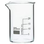 Borosilicate Glass Beaker
 Plastic Beaker (Euro Design)
 Plastic Beaker (Printed Graduation)
 Test Tube Brush
 Measuring Cylinder Brush
 Conical Flask Brush
 Volumetric Flask Brush
 Round Bottom Flask Brush
 Glass Beaker Brush
 Pipette Brush
 Wash Bottle Brush
 Borosilicate Büchner Flask
 Borosilicate Erlenmeyer/Conical Flask
 Borosilicate Pear-Shaped Flask
 Borosilicate Round Bottom Flask
 Plastic Conical Flask
 Plastic Volumetric Flask
 Bunsen Burner
 Spirit Lamp
 Borosilicate Glass Burette
 Plastic Burette
 Capillary Tube
 Centrifuge Tube
 Test Tube
 Ria Vial
 Vacutainer Tubes
 Syringes
 Student Microscope
 Binocular Microscope
 Dissecting Microscope
 Microscope Glass Slides
 Cover Slip
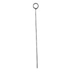 Inoculating Loop
 Slide Box
 Lamps
Lamps
 Oils
Oils
 Beaker Tongs
 Crucible Tongs
 Flask Tongs
 Borosilicate Glass Funnel
 Plastic Funnels
 Wash Bottle
 Borosilicate Glass Reagent Bottle
 Plastic Reagent Bottle
 Borosilicate Measuring Cylinder
 Plastic Measuring Cylinder
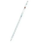
 Borosilicate Glass Graduated Pipette
 Borosilicate Glass Volumetric Pipette
 HB Pipette
 Pasteur Pipette
 Micropipettes
 Micropipette Tips
 Filter Paper
 Litmus Paper
 pH Paper
 Chromatography Paper
 Plastic Petri Plates (Sterile)
 Glass Petri Plates (Non-Sterile)
 Safety Goggles
 Lab Coats
 Gloves
 Masks
Masks
 Shoe Covers
 Hair & Beard Covers
 Steel Spatula
 Plastic Spatula
 Hitachi Sample Cup
 Plastic Scoop
 Plastic Medicine Cup
 Dissecting Tool Kit
 Dissecting Forceps
 Hemostatic Forceps
 Thumb Forceps / Tweezers
 Blood Culture Bottle
 Urine Container
 Wooden Swab Stick
 Test Tube Holder
 Test Tube Racks
 Magnifying Glass
 Watch Glass
 Mortar and Pestle
 Coplin Jar
 Plastic Stirrer
 Glass Stirrer
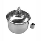
 Crucible
 Tripod
 Wire Mesh
 Laboratory Thermometer
 Tourniquet
 Alcohol Swab
 Blood Lancet
 Bandage
 Gloves & Masks


Ohm’s Law Principle: Unveiling Electrical Relationships in Circuits
Contents
- Introduction to Ohm’s Law Principle
- Historical Background of Ohm’s Law
- Understanding the Core Concept of Electrical Resistance
- Relationship Between Voltage, Current, and Resistance
- Mathematical Expression of Ohm’s Law
- Explanation of Voltage in Electrical Circuits
- Understanding Electric Current Flow
- What Is Resistance and How It Affects Circuits
- Graphical Representation of Ohm’s Law
- Ohm’s Law in Series Circuits
- Ohm’s Law in Parallel Circuits
- Practical Applications of Ohm’s Law in Daily Life
- Role of Ohm’s Law in Electrical Engineering
- Limitations and Conditions of Ohm’s Law
- Factors Affecting Resistance in Conductors
- Common Mistakes While Applying Ohm’s Law
- Difference Between Ohm’s Law and Kirchhoff’s Laws
- Importance of Ohm’s Law in Circuit Analysis
- Solved Examples Based on Ohm’s Law
- Real-World Examples of Ohm’s Law in Action
- Advantages of Using Ohm’s Law for Circuit Design
- Safety Considerations When Applying Ohm’s Law
- Conclusion
- Frequently Asked Questions About Ohm’s Law Principle
Introduction to Ohm’s Law Principle
Electricity flows through our lives like a silent current, powering everything from our smartphones to the lights in our homes. But have you ever stopped to think about what makes that electricity work? At the heart of this intricate dance is Ohm’s Law—a fundamental principle that unveils the relationships between voltage, current, and resistance. Understanding these concepts not only demystifies how circuits operate but also empowers us to harness electrical energy more effectively.
Whether you’re an aspiring engineer or someone simply curious about the mechanics of your gadgets, exploring Ohm’s Law opens up a world of insights into how we interact with technology every day. Join us on this enlightening journey as we delve into the historical roots, core principles, and practical applications of this remarkable law governing electrical circuits.
Historical Background of Ohm’s Law
Ohm’s Law, a fundamental principle in electrical engineering, traces its origins back to the early 19th century. It is named after Georg Simon Ohm, a German physicist and mathematician who published his groundbreaking work in 1827.
In his book “Die galvanische Kette,” Ohm explored the behavior of electric circuits. His meticulous experiments led him to discover the relationship between voltage, current, and resistance. This was revolutionary at a time when electricity was becoming central to technological advancements.
Before Ohm’s contributions, understanding electricity was largely theoretical and lacked precise mathematical interpretation. His findings laid the groundwork for future research in electronics and paved the way for innovations that followed.
Ohm’s principles were initially met with skepticism but gradually gained acceptance as engineers recognized their practical significance in circuit design and analysis. Today, they remain foundational in both education and application within various fields of technology.
Understanding the Core Concept of Electrical Resistance
Electrical resistance is a fundamental concept that dictates how much current can flow through a conductor. It acts like a barrier, opposing the movement of electric charge. The higher the resistance, the less current will pass for a given voltage.
Materials vary significantly in their ability to resist electrical flow. Conductors, such as copper and aluminum, have low resistance, allowing electricity to move freely. Insulators like rubber or glass exhibit high resistance and restrict electron movement.
Resistance depends on several factors including temperature and material composition. As temperature rises, so does the atomic vibration within materials; this can increase resistance in conductors but may decrease it in some semiconductors.
Understanding this core principle helps engineers design more efficient circuits by selecting appropriate materials and configurations to manage energy use effectively. This knowledge is vital for both everyday applications and advanced technological developments.
Relationship Between Voltage, Current, and Resistance
Voltage, current, and resistance form the foundation of Ohm’s Law. Each element plays a unique role in how electrical circuits operate.
Voltage, often referred to as electric potential difference, pushes electric charges through a conductor. It’s like the pressure that drives water through a pipe.
Current is the flow of those charges. Measured in amperes (A), it indicates how much charge passes through a point over time.
Resistance comes into play by opposing this flow. It measures how difficult it is for current to pass through materials, expressed in ohms (Ω). Higher resistance means less current flows for a given voltage.
These three concepts are interconnected; altering one affects the others directly. Increase voltage while keeping resistance constant? Current rises accordingly. Reduce resistance at fixed voltage? Again, current increases.
Understanding their relationship is essential for designing effective electrical systems and troubleshooting issues within circuits.
Mathematical Expression of Ohm’s Law
Ohm’s Law is elegantly captured in its mathematical expression: V = I × R. Here, V represents voltage measured in volts, I denotes current in amperes, and R signifies resistance in ohms.
This equation forms the backbone of electrical engineering. It illustrates how these three fundamental elements interact within a circuit.
When you increase the voltage, while keeping resistance constant, the current rises proportionally. Conversely, if resistance increases with a fixed voltage, less current will flow through the circuit.
Understanding this relationship facilitates better design decisions for electrical systems. Engineers rely on this formula to calculate optimal values for circuits and troubleshoot issues effectively.
Being able to manipulate these variables allows for greater control over electronics performance and efficiency. Mastering this basic yet powerful equation is crucial for anyone delving into electrical concepts or applications.
Explanation of Voltage in Electrical Circuits
Voltage, often referred to as electric potential difference, is a crucial element in understanding electrical circuits. It represents the energy per unit charge available to move electrons through a conductor. You can think of voltage as the push that drives current along wires.
When two points in a circuit have different electric potentials, voltage creates an imbalance. This imbalance encourages electrons to flow from higher potential areas to lower ones, resulting in electric current. Essentially, it’s this movement of charges that powers our devices.
In practical terms, measuring voltage helps assess how much energy is available for work within a circuit. Voltmeters are typically used for these measurements and provide essential information needed when troubleshooting or designing systems. Understanding voltage allows engineers and electricians alike to determine if enough power exists for proper operation without risking damage from overloads or insufficient supply.
Understanding Electric Current Flow
Electric current flow is the movement of electric charge through a conductor, typically driven by voltage. When a circuit is complete, electrons start to move from the negative terminal of a power source toward the positive terminal. This creates what we know as an electric current.
The flow can be direct (DC) or alternating (AC). Direct current flows in one direction, while alternating current changes its direction periodically. Each type has distinct applications and characteristics affecting how devices operate.
Current is measured in amperes (A), indicating how many coulombs pass through a point per second. A strong understanding of this concept helps engineers design efficient circuits and troubleshoot issues effectively.
Factors such as temperature and material type can influence current flow significantly. Understanding these nuances enables smarter choices when working on electrical systems or experimenting with new technologies.
What Is Resistance and How It Affects Circuits
Resistance is a fundamental property of materials that impedes the flow of electric current. It’s measured in ohms and varies significantly among different substances. Conductors like copper have low resistance, allowing electrons to move freely, while insulators such as rubber exhibit high resistance.
In electrical circuits, resistance plays a critical role. High resistance can limit current flow, affecting how devices operate. For instance, if too much resistance is present in a circuit designed for low power, it might not function properly or could even fail.
Moreover, temperature can influence resistance levels. As temperatures rise, many materials experience increased atomic vibrations that hinder electron movement. This effect needs consideration when designing circuits to ensure they remain efficient under various conditions.
Understanding how resistance interacts with other elements in a circuit helps engineers design safer and more effective systems tailored to specific applications.
Graphical Representation of Ohm’s Law
Graphical representation of Ohm’s Law provides a visual understanding of the relationship between voltage, current, and resistance. Typically illustrated on a graph with voltage (V) on the y-axis and current (I) on the x-axis, it forms a straight line.
This linearity indicates that as voltage increases, current also rises proportionally. The slope of this line represents resistance (R), which can be calculated using the formula R = V/I.
A steeper slope signifies higher resistance; conversely, a gentle slope shows lower resistance. This visualization aids in quickly identifying how changes in one variable affect another.
When analyzing circuits or designing systems, these graphs help engineers and students alike to predict behaviors efficiently. Understanding this graphical approach enhances comprehension of circuit dynamics beyond mathematical equations alone.
Ohm’s Law in Series Circuits
In series circuits, components are connected end-to-end, forming a single path for current to flow. This configuration directly influences the application of Ohm’s Law.
When resistors are arranged in series, their total resistance is simply the sum of individual resistances. This means that as you add more resistors, the overall resistance increases. Consequently, this affects how voltage and current behave within the circuit.
Ohm’s Law tells us that voltage drop across each resistor is proportional to its resistance. Therefore, if one component has a higher resistance than another, it will experience a greater share of the total voltage supplied by the source.
This characteristic can be vital in designing circuits where specific voltages must be maintained across different devices. Understanding these dynamics helps engineers ensure reliability and functionality in electrical systems.
Ohm’s Law in Parallel Circuits
Ohm’s Law plays a crucial role in understanding parallel circuits. In these setups, multiple components share the same voltage across them while allowing current to divide among pathways.
When you add resistors in parallel, the total resistance decreases. This is because each additional pathway offers an alternative route for the electric current. More routes lead to greater overall conductivity.
Calculating total resistance in a parallel circuit involves using the formula: 1/R_total = 1/R1 + 1/R2 + 1/R3… This means that even if one resistor fails, current can still flow through other paths.
The voltage remains constant across all components, ensuring they operate under similar conditions. However, individual currents may vary depending on their respective resistances.
Understanding this relationship helps engineers design safer and more efficient electrical systems where reliability is key.
Related Products


Practical Applications of Ohm’s Law in Daily Life
Ohm’s Law is not just a theoretical principle; it has real-world implications that touch our daily lives in various ways. Take, for instance, the simple act of charging your smartphone. Understanding voltage and current helps you choose the right charger for efficient power transfer.
In household wiring, electricians apply Ohm’s Law to ensure circuits are safe and functional. By calculating resistance and understanding how devices interact within the circuit, they prevent overloads that could lead to electrical fires.
Moreover, hobbyists often rely on Ohm’s Law when building projects like DIY electronics or model trains. It allows them to predict how components will behave under different conditions.
Even in automotive systems, mechanics use this principle for troubleshooting electrical issues. A quick calculation can help identify faulty sensors or failing batteries before more extensive repairs are needed.
Role of Ohm’s Law in Electrical Engineering
Ohm’s Law serves as a foundational principle in electrical engineering, guiding the design and analysis of circuits. Engineers rely on this law to predict how voltage, current, and resistance interact within various components.
In circuit design, Ohm’s Law helps engineers determine optimal values for resistors and other elements. This ensures efficiency while minimizing energy losses. By using the law, they can create systems that perform reliably under different conditions.
Moreover, Ohm’s Law is crucial during troubleshooting processes. When diagnosing faults in a circuit, understanding these relationships allows engineers to identify issues quickly and accurately.
The versatility of Ohm’s Law extends beyond simple circuits; it applies equally well to complex networks found in modern electronics. From consumer devices to large industrial machinery, its principles help maintain functionality across diverse applications.
Limitations and Conditions of Ohm’s Law
Ohm’s Law is a powerful tool, but it does have its limitations. It primarily applies to linear components where resistance remains constant. Many materials do not behave this way under varying conditions.
Temperature changes can significantly affect resistance in conductors. For instance, as temperature rises, the resistance of most metals increases, which alters the relationship described by Ohm’s Law.
Non-linear devices like diodes and transistors challenge the law further. Their behavior cannot be accurately predicted using simple voltage-current-resistance calculations.
Additionally, at very high frequencies or in complex circuits involving capacitance and inductance, Ohm’s Law may not apply directly.
Understanding these limitations is crucial for engineers and technicians when designing circuits or troubleshooting issues. Recognizing when Ohm’s Law holds true ensures more accurate electrical analysis and application.
Factors Affecting Resistance in Conductors
Resistance in conductors isn’t a one-size-fits-all scenario. Several factors come into play, shaping how electricity flows through different materials.
First, the type of material matters significantly. Metals like copper and aluminum boast low resistance due to their abundance of free electrons. Conversely, rubber and glass are insulators with high resistance levels.
Temperature also influences resistance. As temperature rises, atoms vibrate more vigorously, making it harder for electrons to pass through. This phenomenon generally leads to increased resistance in most conductive materials.
Length is another crucial factor; longer wires offer more opposition to current flow than shorter ones do. Moreover, the thickness or cross-sectional area plays a role as well—thicker wires typically allow for easier electron movement.
Impurities within a conductor can introduce additional obstacles for flowing charges. The quality of the material significantly affects electrical performance in real-world applications.
Common Mistakes While Applying Ohm’s Law
When working with Ohm’s Law, many people trip over common pitfalls. One frequent mistake is miscalculating units. Voltage, current, and resistance must always be in compatible units—volts for voltage, amperes for current, and ohms for resistance.
Another error involves neglecting the context of materials. Different conductors exhibit varying resistances under similar conditions. Assuming a uniform behavior can lead to faulty conclusions.
Misinterpretation of circuit configurations also occurs often. For instance, confusing series and parallel circuits can lead to incorrect calculations of total resistance or current flow.
Some users overlook temperature effects on resistance. As temperatures rise, so does the resistance in most materials—a critical factor in precise calculations that’s sometimes ignored. These mistakes not only hinder learning but can also cause inefficiencies in real-world applications.
Difference Between Ohm’s Law and Kirchhoff’s Laws
Ohm’s Law and Kirchhoff’s Laws are essential in understanding electrical circuits, but they serve different purposes.
Ohm’s Law focuses on the relationship between voltage, current, and resistance in a single component or circuit. It simplifies how we calculate these values when dealing with resistive elements.
On the other hand, Kirchhoff’s Laws delve deeper into circuit analysis. Kirchhoff’s Current Law (KCL) addresses the flow of electric charge at junctions within a circuit. It states that the total current entering a junction equals the total current exiting it.
Kirchhoff’s Voltage Law (KVL) examines closed loops within circuits. This law asserts that the sum of all voltages around any closed loop is equal to zero.
Together, these laws complement each other for comprehensive circuit analysis but tackle distinct aspects of electrical systems.
Importance of Ohm’s Law in Circuit Analysis
Ohm’s Law serves as the backbone of circuit analysis. It simplifies our understanding of electrical systems by establishing clear relationships between voltage, current, and resistance.
Engineers rely on this principle to design efficient circuits and troubleshoot issues effectively. Without it, navigating complex networks would be far more challenging.
In practice, Ohm’s Law allows for quick calculations that determine how components will behave under varying conditions. This adaptability is crucial in developing both simple and intricate electronic devices.
Understanding these relationships also helps predict potential failures or performance bottlenecks within a circuit. By applying Ohm’s Law, professionals can ensure that their designs operate safely and efficiently.
Embracing this fundamental law enhances not only theoretical knowledge but practical application in engineering fields across the board.
Solved Examples Based on Ohm’s Law
Let’s explore some practical examples to deepen our understanding of Ohm’s Law.
Imagine a simple circuit with a battery providing 12 volts and a resistor of 4 ohms. To find the current flowing through this circuit, we use Ohm’s Law: \( I = \frac{V}{R} \). Plugging in the values gives us \( I = \frac{12V}{4Ω} = 3A\). This means that 3 amperes flow through the circuit.
Now consider another scenario with two resistors in series, one at 2 ohms and another at 6 ohms, connected to a 16-volt source. The total resistance is the sum: \( R_{total} = R_1 + R_2 = 2Ω + 6Ω = 8Ω \). Using Ohm’s Law again, we find the current as \( I = \frac{16V}{8Ω} = 2A\).
These examples illustrate how versatile and applicable Ohm’s Law can be in real-world situations.
Real-World Examples of Ohm’s Law in Action
Ohm’s Law finds its way into our daily lives in various practical scenarios. Take a simple flashlight, for instance. When you insert new batteries, the voltage increases, leading to a brighter light. This is Ohm’s Law at work—higher voltage results in higher current flow.
In homes, ohm’s law plays a crucial role when using appliances like heaters or air conditioners. The resistance within these devices determines how much electrical energy they consume based on their rated voltage and desired current output.
Traffic lights also use this principle subtly. Engineers design them with specific resistances to ensure that the correct amount of electric current flows through each bulb, maintaining visibility while conserving energy.
Even in electric vehicles, Ohm’s Law helps optimize battery performance by adjusting the power drawn depending on driving conditions. Such applications highlight how essential this principle is across different fields and everyday situations.
Advantages of Using Ohm’s Law for Circuit Design
Ohm’s Law is a cornerstone in circuit design, providing crucial insights into electrical relationships. Its simplicity makes it accessible for both beginners and seasoned engineers.
Designers rely on this principle to calculate the right voltage and current for components. This ensures devices operate efficiently without overheating or failing.
Using Ohm’s Law helps predict how changing one element affects others in a circuit. Such foresight allows for smoother adjustments during testing phases.
Another advantage lies in troubleshooting. When issues arise, understanding these fundamental relationships aids quick identification of faults.
Moreover, applying Ohm’s Law streamlines the design process. It reduces trial-and-error efforts by offering reliable calculations upfront, saving time and resources.
This law fosters innovation by encouraging designers to experiment within safe operational limits while ensuring compliance with safety standards.
Safety Considerations When Applying Ohm’s Law
When working with Ohm’s Law, safety should always be a priority. Understanding the relationship between voltage, current, and resistance is crucial to prevent accidents.
High voltages can lead to severe electrical shocks. Always ensure that circuits are de-energized before making any adjustments or measurements. Use insulated tools and wear appropriate personal protective equipment.
Be cautious of overheating components. Excessive current flow can cause resistors or wires to heat up excessively, leading to potential fire hazards. Regularly check for signs of damage in your circuit elements.
It’s also essential to use reliable measuring devices when assessing voltage and current levels. Faulty equipment might provide misleading readings, putting you at risk.
Familiarize yourself with the specific limits of each component in your circuit system. Adhering to these guidelines will help maintain a safe working environment while applying Ohm’s Law effectively.
Conclusion
Ohm’s Law remains a cornerstone of electrical engineering and circuit design. Its principles help us navigate the complexities of currents and voltages in various applications.
Understanding how voltage, current, and resistance interrelate enables both professionals and hobbyists to create effective circuits. The beauty lies in its simplicity; a few equations can unlock vast possibilities.
As technology evolves, so does our understanding of these concepts. New materials and methods continuously challenge traditional views yet reinforce Ohm’s foundational role.
Whether you’re fixing household items or designing sophisticated systems, this principle offers invaluable insights into electrical behavior. It empowers users to innovate while ensuring safety standards are met.
The impact is far-reaching—shaping not only devices we use daily but also inspiring future advancements in the field of electricity. Embracing this knowledge fosters creativity and progress for generations to come.
Frequently Asked Questions About Ohm’s Law Principle
Understanding Ohm’s Law can greatly enhance your grasp of electrical circuits and their behavior. Whether you’re a student, an aspiring engineer, or simply curious about the principles governing electricity, this foundational concept offers invaluable insights.
Here are some frequently asked questions about Ohm’s Law:
What is Ohm’s Law?
Ohm’s Law states that the current flowing through a conductor between two points is directly proportional to the voltage across the two points and inversely proportional to the resistance of the conductor.
How do you calculate ohms?
To find ohms (the unit for resistance), you can rearrange Ohm’s Law as Resistance (R) = Voltage (V) / Current (I). Simply divide voltage by current to get your answer in ohms.
Is Ohm’s Law applicable for all materials?
No, not all materials follow Ohm’s Law. Non-ohmic materials exhibit a nonlinear relationship between voltage and current due to changes in temperature or other factors.
Can I apply Ohm’s law with alternating current (AC)?
Yes, but it requires additional considerations such as impedance instead of resistance because AC circuits can involve capacitors and inductors which affect total opposition to flow.
Why is understanding resistance important?
Resistance plays a critical role in determining how much energy loss occurs within an electrical circuit due to heat dissipation when electric currents flow through resistive components.
 Cardiology
 Clinical Oncology