
-
-
 Cardiology
-
 Clinical Oncology
-
 Dental
-
 Dermatology
-
 Ear, Nose, Throat (ENT)
-
 Endocrinology
-
 Gastroenterology
-
 General Surgery
-
 Gynecology & Obstetrics
-
 Interventional Cardiology
-
 Nephrology
-
 Neurology
-
 Oncology Surgery
-
 Ophthalmology
-
 Orthopedics
-
 Pediatrics
-
 Pediatrics Surgery
-
 Physiotherapy
-
 Plastic Surgery
-
 Psychiatry & Psychology
-
 Radiology
-
 Urology
-
 Vascular Surgery
-

 Anatomy Lab Equipments
 Biochemistry Lab Equipments
 Biology Lab Equipments
 Chemistry Lab Equipments
 Cytology Lab Equipments
 Cytopathology Lab Equipments
 Dental Lab Equipments
 Forensic Lab Equipments
 Genetics Lab Equipments
 Hematology Lab Equipments
 Histology Lab Equipments
 Histopathology Lab Equipments
 Mathematics Lab Equipments
 Microbiology Lab Equipments
 Molecular Biology Lab Equipments
 Pathology Lab Equipments
 Pharmaceutical Lab Equipments
 Physics Lab Equipments
 Radiology Lab Equipments
 Science Lab Kit’s
 Toxicology Lab Equipments

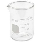
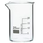 Borosilicate Glass Beaker
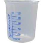 Plastic Beaker (Euro Design)
 Plastic Beaker (Printed Graduation)
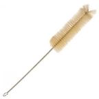
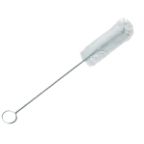 Test Tube Brush
 Measuring Cylinder Brush
 Conical Flask Brush
 Volumetric Flask Brush
 Round Bottom Flask Brush
 Glass Beaker Brush
 Pipette Brush
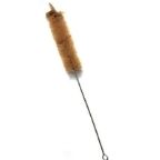 Wash Bottle Brush
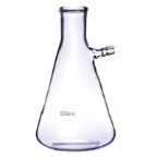
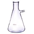
 Borosilicate Büchner Flask
 Borosilicate Erlenmeyer/Conical Flask
 Borosilicate Pear-Shaped Flask
 Borosilicate Round Bottom Flask
 Plastic Conical Flask
 Plastic Volumetric Flask
 Bunsen Burner
 Spirit Lamp
 Borosilicate Glass Burette
 Plastic Burette
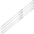
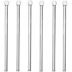
 Capillary Tube
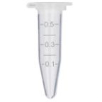 Centrifuge Tube
 Test Tube
 Ria Vial
 Vacutainer Tubes
 Syringes
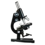
 Student Microscope
 Binocular Microscope
 Dissecting Microscope
 Microscope Glass Slides
 Cover Slip
 Inoculating Loop
 Slide Box
 Lamps
Lamps
 Oils
Oils
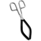 Beaker Tongs
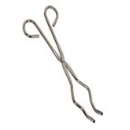 Crucible Tongs
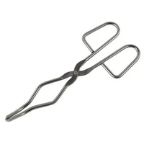 Flask Tongs
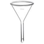 Borosilicate Glass Funnel
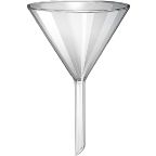 Plastic Funnels
 Wash Bottle
 Borosilicate Glass Reagent Bottle
 Plastic Reagent Bottle
 Borosilicate Measuring Cylinder
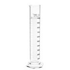 Plastic Measuring Cylinder
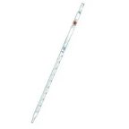
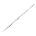 Borosilicate Glass Graduated Pipette
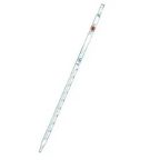
 Borosilicate Glass Volumetric Pipette
 HB Pipette
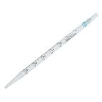
 Pasteur Pipette
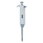
 Micropipettes
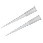 Micropipette Tips
 Filter Paper
 Litmus Paper
 pH Paper
 Chromatography Paper
 Plastic Petri Plates (Sterile)
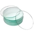
 Glass Petri Plates (Non-Sterile)
 Safety Goggles
 Lab Coats
 Gloves
 Masks
Masks
 Shoe Covers
 Hair & Beard Covers
 Steel Spatula
 Plastic Spatula
 Hitachi Sample Cup
 Plastic Scoop
 Plastic Medicine Cup
 Dissecting Tool Kit
 Dissecting Forceps
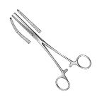 Hemostatic Forceps
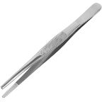
 Thumb Forceps / Tweezers
 Blood Culture Bottle
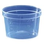
 Urine Container
 Wooden Swab Stick
 Test Tube Holder
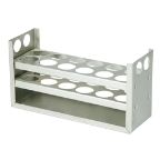 Test Tube Racks
 Magnifying Glass
 Watch Glass
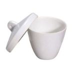
 Mortar and Pestle
 Coplin Jar
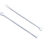 Plastic Stirrer
 Glass Stirrer
 Crucible
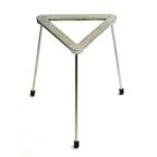 Tripod
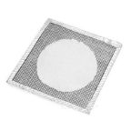 Wire Mesh
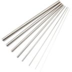
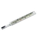 Laboratory Thermometer
 Tourniquet
 Alcohol Swab
 Blood Lancet
 Bandage
 Gloves & Masks


Magnetic Stirrer Diagram: Understanding Its Mechanism

Contents
- Introduction to Magnetic Stirrer and Its Working Principle
- What Is a Magnetic Stirrer Diagram?
- Importance of Magnetic Stirrer Diagrams in Laboratory Applications
- Key Components Shown in a Magnetic Stirrer Diagram
- Magnetic Stirrer Base Unit Explained
- Role of the Rotating Magnetic Field in Stirring
- Function of the Stir Bar (Magnetic Follower)
- How the Motor Drives the Magnetic Stirrer Mechanism
- Understanding Speed Control Through the Diagram
- Heat Plate Integration in Magnetic Stirrer Diagrams
- Electrical Circuit Representation in Magnetic Stirrer Systems
- Step-by-Step Working Mechanism Illustrated in the Diagram
- Types of Magnetic Stirrers and Their Diagram Differences
- Digital vs Analog Magnetic Stirrer Diagrams
- Safety Features Highlighted in Magnetic Stirrer Diagrams
- Common Symbols and Labels Used in Magnetic Stirrer Diagrams
- Applications of Magnetic Stirrer Diagrams in Education and Research
- Advantages of Using Diagram-Based Understanding
- Limitations of Magnetic Stirrer Mechanism Explained Visually
- Troubleshooting Magnetic Stirrer Issues Using Diagrams
- Maintenance Insights Derived from Magnetic Stirrer Diagrams
- How to Read and Interpret a Magnetic Stirrer Diagram Correctly
- Frequently Asked Questions About Magnetic Stirrer Diagram
Introduction to Magnetic Stirrer and Its Working Principle
A magnetic stirrer is a widely used laboratory instrument designed to mix liquids efficiently without direct manual contact. It works on a simple yet effective principle—magnetic coupling. Inside the magnetic stirrer base, a rotating magnetic field is generated using an internal motor and magnet.
When a magnetic stir bar (also called a flea) is placed inside a liquid-filled container, it follows this rotating field and stirs the solution smoothly.
Magnetic stirrers are preferred in laboratories because they provide consistent mixing, reduced contamination risk, and hands-free operation. They are commonly used in chemistry labs, pharmaceutical research, educational institutions, and industrial testing labs.
Understanding the magnetic stirrer diagram helps users visualize how internal components work together, ensuring correct usage, safety, and optimal performance during experiments.
What Is a Magnetic Stirrer Diagram?
A magnetic stirrer diagram is a visual representation that explains the internal and external components of a magnetic stirrer and how they function together. It typically illustrates the base unit, rotating magnet, motor, control panel, power supply, and the magnetic stir bar placed inside the beaker.
For students, technicians, and lab professionals, this diagram simplifies complex mechanisms into an easy-to-understand layout. Instead of relying only on theory, the diagram shows how motion is transferred wirelessly from the base to the liquid.
In laboratory e-commerce platforms, magnetic stirrer diagrams play an important role in product listings by helping buyers quickly understand product functionality before purchase. A clear diagram enhances product transparency and builds trust with customers.
Importance of Magnetic Stirrer Diagrams in Laboratory Applications
Magnetic stirrer diagrams are extremely important in laboratory environments where accuracy and safety matter. These diagrams help users understand correct placement of glassware, proper speed control, and the relationship between the stirrer base and the stir bar.
In teaching laboratories, diagrams act as educational tools, helping students grasp practical concepts quickly. In research and industrial labs, they support equipment standardization and proper training. From an e-commerce perspective, including diagrams improves user experience, reduces product return rates, and increases buyer confidence.
Many lab managers rely on diagrams to compare models, understand load capacity, and check compatibility with heating plates. Overall, a magnetic stirrer diagram ensures correct usage, prevents equipment misuse, and improves laboratory efficiency.
Key Components Shown in a Magnetic Stirrer Diagram
A well-labeled magnetic stirrer diagram highlights several essential components. The stirrer base houses the motor and internal magnet responsible for generating the rotating magnetic field. The control panel allows users to adjust stirring speed and, in some models, temperature.
The magnetic stir bar, placed inside the container, is coated with chemically resistant material like PTFE to ensure durability and safety. Some diagrams also show cooling vents, power indicators, and heating elements in hot plate magnetic stirrers.
Understanding these components through a diagram helps users select the right stirrer for specific lab needs, whether it’s basic mixing or temperature-controlled reactions.
Magnetic Stirrer Base Unit Explained
The magnetic stirrer base unit is the core of the entire system. Inside the base, an electric motor rotates a magnet or set of magnets, creating a magnetic field above the surface. This field drives the stir bar placed in the liquid, enabling smooth and uniform mixing.
Most base units are designed with chemical-resistant surfaces to withstand spills and harsh lab conditions. Advanced models include digital speed control, overload protection, and heat regulation features.
From a laboratory e-commerce standpoint, the base unit’s quality determines performance, durability, and long-term value. A magnetic stirrer diagram clearly explains the base unit’s internal mechanism, helping buyers make informed decisions and ensuring correct operation in laboratory workflows.
Role of the Rotating Magnetic Field in Stirring
The rotating magnetic field is the core principle behind the operation of a magnetic stirrer. In a magnetic stirrer diagram, this field is generated by magnets attached to a rotating motor beneath the stirrer plate.
When the motor spins, it creates a rotating magnetic field that passes through the stirrer plate and interacts with the magnetic stir bar inside the container. This interaction causes the stir bar to rotate smoothly with the field.
This contactless stirring method reduces contamination risks and ensures uniform mixing of solutions. The rotating magnetic field allows consistent vortex formation, which is crucial for chemical reactions, sample preparation, and solution homogenization.
Understanding this part of the diagram helps users appreciate why magnetic stirrers are preferred over manual or mechanical stirring methods in modern laboratories.
Function of the Stir Bar (Magnetic Follower)
The stir bar, also known as a magnetic follower, is a small, magnetized rod placed inside the liquid container. In a magnetic stirrer diagram, it appears directly above the rotating magnetic field.
As the field rotates, the stir bar follows its motion, creating continuous agitation of the liquid. Stir bars are usually coated with chemically resistant materials like PTFE to prevent corrosion and contamination.
Different stir bar shapes and sizes are designed for specific container volumes and viscosities. The correct selection of a stir bar ensures efficient mixing without slipping or decoupling from the magnetic field.
Understanding the stir bar’s function helps laboratory users achieve better mixing results, reduce experiment errors, and extend the lifespan of their magnetic stirrer equipment.
How the Motor Drives the Magnetic Stirrer Mechanism
The motor is the driving force behind the magnetic stirrer mechanism. In a magnetic stirrer diagram, the motor is positioned beneath the top plate and connected to a rotating magnet assembly. When powered on, the motor converts electrical energy into rotational motion, which spins the internal magnets and creates the rotating magnetic field.
High-quality magnetic stirrers use precision motors to ensure stable speed, low vibration, and quiet operation. The motor’s efficiency directly affects stirring consistency, especially during long laboratory procedures.
Understanding the motor’s role helps buyers evaluate performance specifications such as RPM range, load capacity, and durability. This knowledge is especially useful when selecting magnetic stirrers for continuous or heavy-duty laboratory applications.
Understanding Speed Control Through the Diagram
Speed control is a critical feature shown in a magnetic stirrer diagram. It regulates how fast the motor rotates, which directly controls the speed of the magnetic field and stir bar. Speed control may be manual (knob-based) or digital, allowing users to adjust stirring intensity based on solution viscosity and experiment requirements.
Proper speed control prevents splashing, overheating, or stir bar decoupling. Advanced magnetic stirrers offer precise speed calibration for repeatable results, which is essential in research and quality-control laboratories.
By understanding speed control through the diagram, users can optimize mixing efficiency, protect samples, and ensure consistent experimental outcomes across multiple laboratory processes.
Heat Plate Integration in Magnetic Stirrer Diagrams
Many magnetic stirrers include an integrated heating plate, clearly illustrated in advanced magnetic stirrer diagrams. The heat plate sits above the motor assembly and allows simultaneous stirring and heating of solutions. This combination is widely used in chemical synthesis, pharmaceutical formulation, and biological research.
The heating element is controlled separately or integrated with the speed control system, allowing precise temperature regulation. Heat-resistant materials ensure uniform heat distribution and user safety.
Understanding heat plate integration helps laboratories choose the right magnetic stirrer for temperature-sensitive applications. For e-commerce buyers, this feature adds value by reducing the need for separate heating equipment and improving laboratory workflow efficiency.
Related Products


Electrical Circuit Representation in Magnetic Stirrer Systems
The electrical circuit representation in a magnetic stirrer diagram shows how power is supplied and controlled within the system. Typically, the circuit includes a power source, speed controller, motor, and control switch. When the device is switched on, electricity flows through the circuit to drive the motor, which generates a rotating magnetic field.
This magnetic field interacts with the stir bar placed inside the container. Advanced magnetic stirrers may include printed circuit boards, digital displays, and feedback sensors for precise speed control.
Understanding the electrical circuit diagram helps technicians identify power flow, diagnose electrical faults, and ensure proper installation. For laboratory buyers, this information is useful in evaluating build quality, energy efficiency, and compatibility with laboratory power standards.
Step-by-Step Working Mechanism Illustrated in the Diagram
A magnetic stirrer diagram clearly illustrates the step-by-step working mechanism of the device. First, electrical power activates the internal motor located beneath the stirring plate. The motor rotates a magnet or magnetic assembly at a controlled speed.
This rotating magnetic field passes through the stirrer plate and couples with the magnetic stir bar placed in the liquid. As the magnetic field rotates, the stir bar spins, creating a consistent vortex that mixes the solution evenly.
The diagram also highlights speed adjustment components that allow users to control stirring intensity. This visual representation helps laboratory personnel understand how smooth, contact-free stirring is achieved, reducing contamination risk and improving mixing accuracy across various laboratory applications.
Types of Magnetic Stirrers and Their Diagram Differences
Magnetic stirrer diagrams vary depending on the type of stirrer being used. Basic laboratory magnetic stirrers have simple motor and magnet assemblies, while hot plate magnetic stirrers include additional heating elements shown in the diagram. Multi-position magnetic stirrers display multiple stirring stations connected to a single control unit.
Overhead magnetic stirrers feature reinforced motor systems designed for higher viscosity solutions. The diagram differences highlight variations in internal layout, power distribution, and control mechanisms.
Understanding these diagram distinctions helps laboratories select equipment that matches their operational needs. For e-commerce buyers, detailed knowledge of stirrer types improves purchasing decisions by aligning diagram features with intended laboratory workflows.
Digital vs Analog Magnetic Stirrer Diagrams
Digital and analog magnetic stirrer diagrams differ mainly in their control and monitoring components. Analog stirrer diagrams typically show mechanical knobs, variable resistors, and basic motor connections for speed control.
Digital magnetic stirrer diagrams include microcontrollers, digital displays, touch panels, and electronic sensors for precise adjustments. Digital systems often feature memory settings, safety alarms, and temperature feedback integration. These elements are clearly represented in their respective diagrams.
Understanding the differences allows laboratory professionals to choose between simplicity and advanced control. For modern laboratories, digital magnetic stirrer diagrams highlight improved accuracy, automation, and user-friendly operation compared to traditional analog designs.
Safety Features Highlighted in Magnetic Stirrer Diagrams
Magnetic stirrer diagrams also emphasize critical safety features designed to protect users and equipment. Common safety elements include thermal cut-off systems, overload protection circuits, and insulated casing components.
In hot plate magnetic stirrers, diagrams show temperature sensors and automatic shutdown mechanisms to prevent overheating. Non-slip bases and sealed electronic compartments are also highlighted to reduce accident risks.
These safety features are especially important in chemical and pharmaceutical laboratories where hazardous substances are handled. By studying safety indicators in magnetic stirrer diagrams, buyers and users can ensure compliance with laboratory safety standards and select reliable equipment suitable for long-term, safe operation.
Common Symbols and Labels Used in Magnetic Stirrer Diagrams
Magnetic stirrer diagrams use standardized symbols and labels to clearly explain internal components and working principles. Common labels include the rotating magnetic field, drive magnet, stir bar, motor unit, speed controller, and power supply.
Arrows are often used to indicate rotational direction and magnetic coupling between the base magnet and the stir bar inside the container. Electrical symbols may represent the motor circuit or control panel.
These visual labels help users quickly identify how motion is transferred without physical contact. Understanding these symbols is essential for students, technicians, and buyers of laboratory equipment, as it improves clarity when comparing models or interpreting product manuals.
Applications of Magnetic Stirrer Diagrams in Education and Research
Magnetic stirrer diagrams play a key role in laboratory education and scientific research. In academic settings, they help students visualize how magnetic force drives uniform mixing of solutions.
Diagrams simplify complex mechanical and electromagnetic concepts, making them easier to understand during practical training. In research environments, diagrams assist scientists in selecting appropriate stirrer models based on speed range, capacity, and heating compatibility.
They are also used in technical documentation, research papers, and lab protocols. For laboratory e-commerce platforms, these diagrams add educational value and build trust by clearly explaining how the equipment functions.
Advantages of Using Diagram-Based Understanding
Diagram-based explanations make magnetic stirrer mechanisms easier to understand than text alone. Visual representation improves learning speed, especially for beginners who may not be familiar with laboratory instruments. Diagrams clearly show component placement, motion flow, and magnetic interaction, reducing confusion during setup and operation.
They also help users avoid misuse by demonstrating correct container positioning and stir bar alignment. For technicians, diagrams support faster maintenance and troubleshooting.
From an e-commerce perspective, diagram-based content improves product transparency, enhances user confidence, and supports informed purchasing decisions, leading to better customer satisfaction and fewer operational errors.
Limitations of Magnetic Stirrer Mechanism Explained Visually
While diagrams are helpful, they may oversimplify the actual limitations of magnetic stirrer mechanisms. Visuals often do not fully represent factors such as liquid viscosity, container shape, or load imbalance, which affect stirring efficiency.
Diagrams may also fail to show heat buildup, magnetic decoupling at high speeds, or performance variation across different materials. Users relying only on diagrams might overlook real-world constraints like maximum volume capacity or compatibility with corrosive chemicals.
Therefore, diagrams should be used alongside technical specifications and usage guidelines to gain a complete understanding of magnetic stirrer performance and operational limits.
Troubleshooting Magnetic Stirrer Issues Using Diagrams
Magnetic stirrer diagrams are valuable tools for identifying and resolving common operational issues. By referring to diagrams, users can check proper alignment between the drive magnet and stir bar when stirring stops unexpectedly. Diagrams help diagnose problems such as magnetic decoupling, uneven rotation, or incorrect container placement.
They also assist in understanding speed controller settings and motor function. For laboratory staff, visual troubleshooting reduces downtime and prevents unnecessary equipment replacement.
In online laboratory equipment stores, providing troubleshooting diagrams enhances customer support, reduces return rates, and improves overall user experience by enabling quick problem resolution.
Maintenance Insights Derived from Magnetic Stirrer Diagrams
Magnetic stirrer diagrams provide valuable insights into proper maintenance and long-term care of laboratory equipment. By visually identifying internal and external components, users can better understand which parts are most prone to wear, such as bearings, drive magnets, and electronic control units.
Diagrams often show ventilation paths and motor placement, helping technicians ensure proper airflow and prevent overheating. Regular inspection based on diagram guidance allows labs to clean surfaces, check alignment, and replace damaged stir bars before performance issues occur.
For laboratory procurement teams and e-commerce buyers, this knowledge reduces downtime and extends equipment lifespan. Understanding maintenance through diagrams also improves safety by helping users detect early signs of malfunction.
In educational and research laboratories, proper maintenance guided by diagrams ensures consistent stirring performance, accurate results, and compliance with laboratory quality standards.
How to Read and Interpret a Magnetic Stirrer Diagram Correctly
Reading a magnetic stirrer diagram correctly requires familiarity with standard laboratory symbols and labeling conventions. Most diagrams start with a top or cross-sectional view, showing the motor, magnetic drive system, and control interface.
Arrows usually indicate rotational movement, while dotted lines may represent magnetic fields or internal wiring paths. Identifying the stir bar’s position relative to the rotating magnet is key to understanding mixing efficiency.
Some diagrams also include scale references to indicate platform size and container compatibility. For laboratory professionals and buyers, interpreting these diagrams helps in comparing different models and understanding performance limits.
It also assists in troubleshooting issues such as uneven stirring or excessive noise. Accurate interpretation ensures the stirrer is used within recommended parameters, improving reliability and protecting sensitive laboratory samples.
Frequently Asked Questions About Magnetic Stirrer Diagram
What is the purpose of a magnetic stirrer diagram?
A magnetic stirrer diagram visually explains the working principle, components, and magnetic interaction that enable uniform liquid mixing.
Can a magnetic stirrer diagram help in equipment selection?
Yes, diagrams help buyers understand design features, capacity, and compatibility before purchasing laboratory stirrers.
Are magnetic stirrer diagrams useful for maintenance?
They guide users in identifying critical components, improving routine inspection, cleaning, and preventive maintenance.
Do all magnetic stirrer diagrams look the same?
No, diagrams vary depending on model type, heating function, speed control, and manufacturer design.
Is technical knowledge required to read a magnetic stirrer diagram?
Basic laboratory knowledge is sufficient, as most diagrams use simple labels and standard symbols for clarity.
 Cardiology
 Clinical Oncology